EDID OVERVIEW &
PRACTICAL APPLICATIONS
PRACTICAL APPLICATIONS
1. What Is EDID?
1.1. The Evolution of EDID
EDID (Extended Display Identification Data) is a standardized data structure defined by VESA. It contains a display’s capabilities-such as vendor information, physical dimensions, color characteristics, supported timings, and more. Its purpose is simple:
EDID allows the display to tell the source “what I can take,” enabling true plug-and-play output.
According to the development chart in page 1 of your draft, EDID evolved through multiple versions, from the original 128-byte structure to enhanced E-EDID with extension blocks and, later, DisplayID designed for next-generation resolutions (8K, VR/AR, etc.).
Its development history is as follows
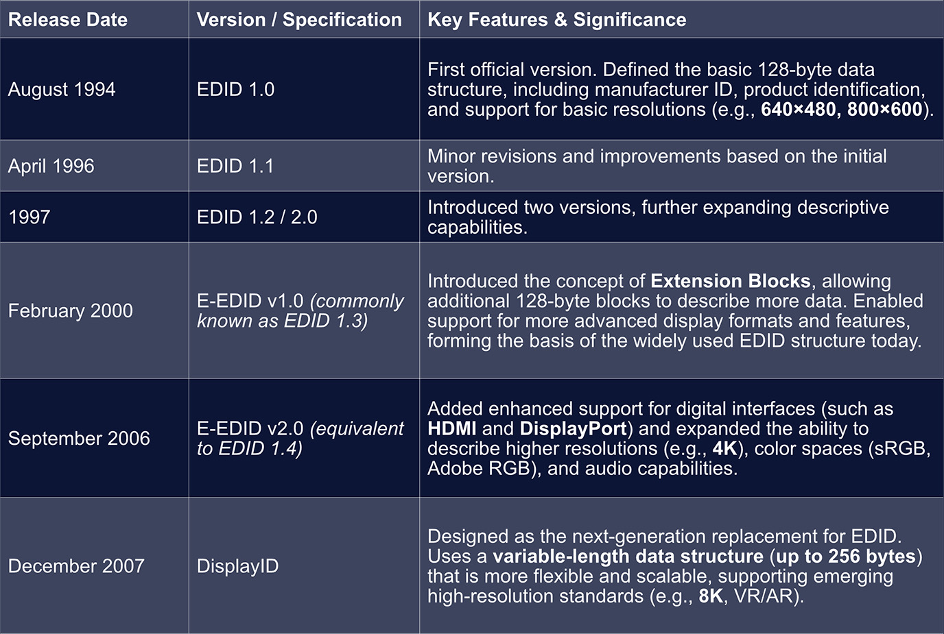
Key Technological Milestones in EDID Evolution
During the evolution of EDID, two major technical breakthroughs fundamentally reshaped how display capability data is described:
• From Fixed to Extensible - The Revolution of E-EDID
The introduction of E-EDID (Enhanced EDID) marked a transformative step.
Beginning with EDID 1.3, extension blocks (most commonly the CEA-861 Extension) were introduced to carry additional capability data required by modern consumer-electronics interfaces such as HDMI. These include audio formats, 3D support, color depth, and other advanced parameters.
This extensible architecture allowed EDID to convey far richer information without changing its core 128-byte base structure.
• Designed for the Future - DisplayID
DisplayID reflects a much more forward-looking design philosophy.
It removes the fixed 128/256-byte limitations entirely and adopts a modular, variable-length structure, making it flexible enough to support any future display format-from ultra-high resolutions to emerging technologies such as VR/AR-without requiring periodic structural “patches.”
1.2 EDID Format Overview
EDID is composed of one or more 128-byte data blocks.
Formula:
Total EDID Size = (1 + Number of Extension Blocks) × 128 bytes
The number of extension blocks is stored in the Extension Flag field located in byte 126 of the Base Block. Byte 127 is the Checksum.
In practical applications, the most common EDID sizes are 128B, 256B, and 384B, though some devices may provide 512B, 640B, or more depending on the required number of extension blocks.
Different EDID sizes simply represent different numbers of blocks, each adding functional descriptions:
1. 128 bytes → Only Block 0 (Base Block)
2. 256 bytes → Block 0 + Block 1 (CTA Extension)
3. 384 bytes → Block 0 + Block 1 + Additional Extension Blocks
1.2.1 Block 0 - Base Block (Fixed 128B, EDID 1.3 / 1.4)
Block 0-the Base Block-is the core container for a display’s identity and essential capability information.
It can be thought of as the display’s “ID card” and “basic specification sheet.”
When a video source (e.g., a GPU) connects to a display, Block 0 is the first block it reads to understand:
• What the display is
• The minimum capabilities it supports
The table below summarizes its primary functional regions (as presented in your original Chinese document):
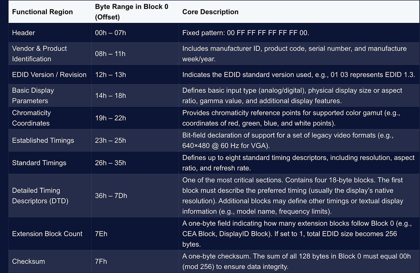
Block 0 provides the fundamental information of a display.
However, modern high-definition displays require additional capability descriptions-such as high-resolution formats, audio support, HDR, and more-which are carried by the CTA Block (Block 1).
1.2.2 Block 1 - CTA-861 Extension (formerly CEA-861, fixed 128 bytes)
In EDID, Block 1 is commonly referred to as the CTA Block (Consumer Electronics Association – Display Information Extension Data Block).
• It follows the standardized extension format defined by the CTA (formerly CEA, now the Consumer Technology Association), and is primarily used to declare advanced A/V capabilities required for modern applications-for example:
• ¡ High-resolution video formats
• ¡ Audio return and multi-channel audio formats
• ¡ HDR and extended colorimetry
Like Block 0, Block 1 is also 128 bytes long, but its structure is far more flexible, adopting a modular format based on multiple Data Blocks, each describing a specific category of capabilities.
• Header (Bytes 0–3)。Block 1 begins with four fixed header bytes:
• ¡ Byte 0: Tag value 0x02, indicating this is a CTA extension block.
• ¡ Byte 1: Revision number of the CEA-861 standard used (e.g., 0x03 for Revision 3).
• ¡ Byte 2: Offset pointing to where the Detailed Timing Descriptors (DTDs) begin.
• ¡ Byte 3: Basic support flags, such as whether the device supports basic audio, YCbCr 4:4:4 output, etc.
• Data Block Collection
Immediately following the header is the Data Block Collection-a sequence of variable-length data blocks, each describing a specific functional category supported by the display.
• Detailed Timing Descriptors (DTDs) & Checksum
After the Data Block Collection, additional DTDs may be included to define more video timings. The final byte of Block 1 is the Checksum, ensuring data integrity.
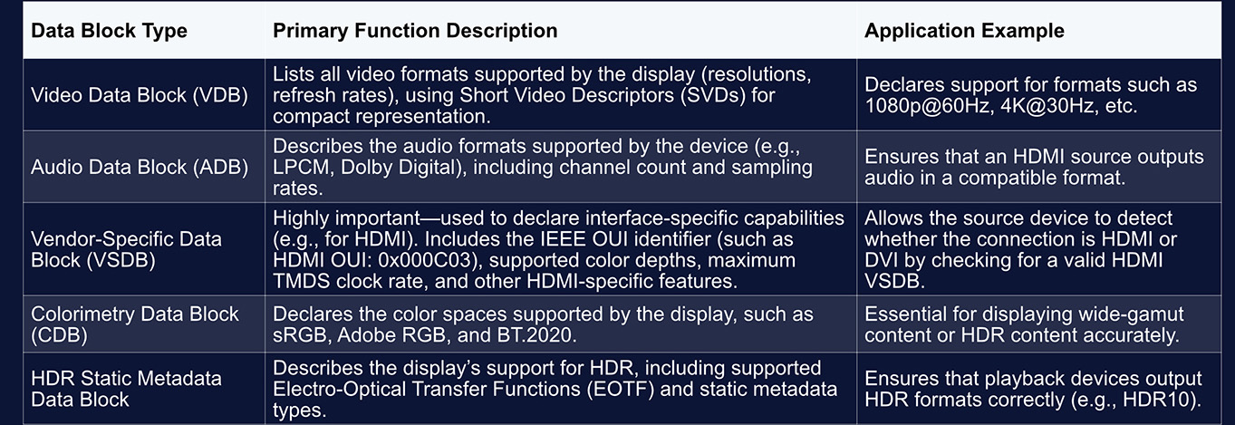
Block 1 conveys a wide range of capabilities through different types of data blocks. Some of the most common types include:
1.2.3 Block 2
Block 2 exists because a 256-byte EDID structure (Block 0 + Block 1) may still be insufficient to describe the most recent and advanced display technologies. Its structure is not fixed, but it typically serves the following purposes:
• Accommodating additional timing information:
For displays that support numerous resolutions, ultra-high refresh rates (e.g., 240 Hz and above), or specialized timing modes-such as professional gaming monitors or VR devices-the single CTA block may not be enough.
Block 2 can extend the CTA block, providing additional Detailed Timing Descriptors (DTDs) or Short Video Descriptors (SVDs) to list more display modes.
• Supporting more advanced display technologies:
To describe cutting-edge capabilities such as 8K resolution, dynamic HDR (e.g., HDR10+), or higher color depths (e.g., 12-bit)-features beyond what the CTA-861 standard originally covers-a more flexible data structure may be used.
Block 2 may be formatted as a DisplayID extension block, which is designed specifically to handle the complexity of future display technologies through a modular, variable-length architecture.
• Carrying vendor-specific data:
Manufacturers may also embed Vendor-Specific Data Blocks (VSDBs) in Block 2 to enable or optimize proprietary functionalities.
In practical use, a DisplayID extension block works alongside the base EDID block, yet most modern operating systems (such as Windows) give higher priority to DisplayID.
If a display provides DisplayID information, the OS typically uses it to configure video output, as it contains more complete and precise capability descriptions.For example, a display that supports 8K + HDR10 may list only a fallback format such as 1080p in its Base EDID, while placing the full 8K/HDR data inside a DisplayID block.
When the GPU reads the EDID, it parses the DisplayID structure to correctly output 8K HDR signals.
1.3 How EDID Is Read
Reading Process:
• HDMI / DVI:
EDID is transmitted over the DDC channel (Display Data Channel), based on the I²C bus
The display supplies 5 V and asserts HPD (Hot Plug Detect) to inform the source: “I am connected-EDID is available.”
Once the system detects the rising edge of HPD, it actively reads the EDID.
• DisplayPort:
Instead of DDC, DP uses the AUX channel to read EDID. The logical process is identical, but the physical layer is different.
• Simplified Handshake Sequence
Power-on → Detect HPD → Read EDID via DDC/AUX → Negotiate resolution/refresh rate/bit depth based on EDID → Establish video link.
This is also why the screen briefly goes black when you hot-plug a display, switch devices, or change cables-the system is re-reading the EDID and renegotiating the output mode.
1.4 Relationship Between EDID and Video Timing Standards (GTF, CVT, CVT-RB)
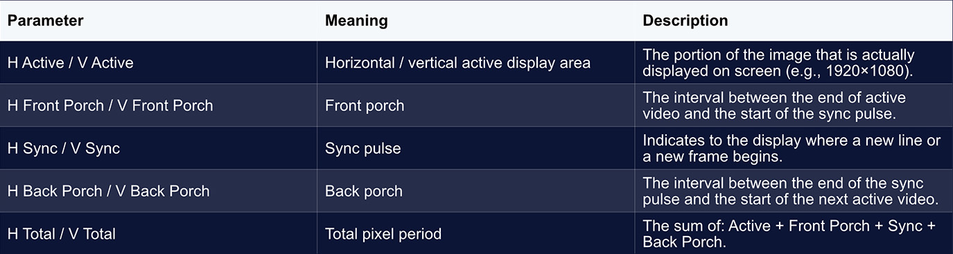
Each “resolution” defined in EDID corresponds to an entire timing profile, including:
Pixel clock、Front porch、Back porch、Sync width and polarity. Even if two timings share the same resolution, their required bandwidth may differ significantly.
Common Timing Standards
• GTF (General Timing Formula):
Older standard with large blanking intervals and higher bandwidth demands.
• CVT (Coordinated Video Timing):
Improved formula with reduced blanking and slightly lower bandwidth.
• CVT-RB (Reduced Blanking):
Significantly compresses porch and sync intervals to reduce bandwidth-ideal for modern LCD displays and high-resolution formats.
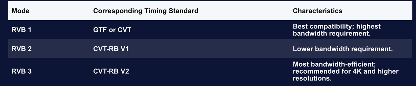
In PixelFlow, the timing presets “RVB1 / RVB2 / RVB3” correspond to these CVT family standards.
They provide simplified options for users to achieve different bandwidth balances at the same resolution.
2. Interface Bandwidth Overview
2.1 Bandwidth Capabilities of Different Interface Types
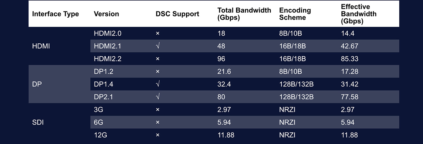
Different video interfaces offer different levels of transmission bandwidth.
This means that, in practical on-site scenarios, the choice of input interface must match the bandwidth required by the video format being used.
A format with higher resolution, higher refresh rate, greater bit depth, or more color channels will demand a higher-bandwidth interface. Below is an overview of the bandwidth characteristics of common video interfaces:
2.2 How to Calculate Effective Bandwidth
For a given input signal, the required effective transmission bandwidth can be calculated using the following formula:
Bandwidth = HTotal × VTotal × Freq × BitDepth × ChnNum
Where:
1. HTotal: The total number of horizontal pixels scanned per line.
Defined as: HTotal = HActive + HSync + HBack Porch + HFront Porch
2. VTotal: The total number of vertical lines scanned per frame.
Defined as: VTotal = VActive + VSync + VBack Porch + VFront Porch
3. Freq: The refresh rate (Hz).
4. BitDepth: The bit depth per color channel (e.g., 8-bit, 10-bit, 12-bit, 16-bit).
5. ChnNum: The number of color channels, depending on the color format:
a. RGB / YUV 4:4:4 → 3 channels
b. YUV 4:2:2 → 2 channels
c. YUV 4:2:0 → 1.5 channels
Example:
Using the CEA standard timing 3840 × 2160 @ 60 Hz, 10-bit, RGB format, the required bandwidth is calculated as follows:
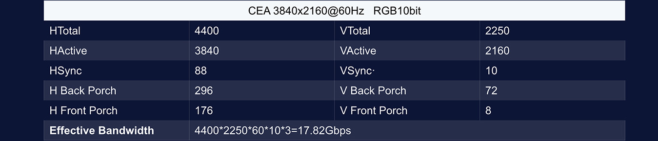
From the above calculation, we can see that the required transmission bandwidth for this format significantly exceeds the effective bandwidth of an HDMI 2.0 interface. Although it also exceeds the effective bandwidth of DP 1.2, the value is relatively close.
In such cases, it is possible to keep VActive and HActive unchanged while adjusting the other timing parameters, enabling the video format to fit within the interface’s bandwidth limitations.
Starting from PixelFlow V1.7.1 and in subsequent versions, the software allows users to directly select different standard timing formats through built-in presets.
Additionally, users can manually select the RVB1, RVB2, and RVB3 timing standards in Custom mode, providing a quick method for adjusting timing parameters in bandwidth-critical scenarios.

3. Video Timing Diagram Explained
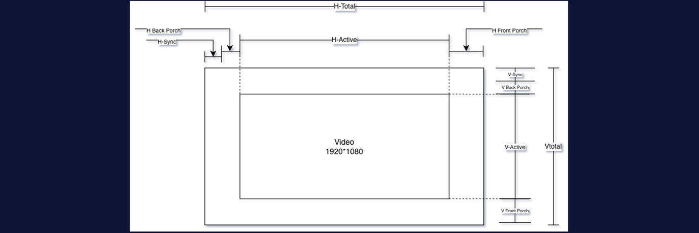
This diagram is a typical Video Timing Diagram, illustrating the structural components of a complete video frame-shown here using 1920×1080 as an example-during the scanning and output process.
3.1 What Are Front Porch, Back Porch, and Sync?
You can think of these intervals as the brief moments when the system “takes a breath, realigns, and signals the next step” after completing the display of a line (or an entire frame) of pixels.
In the era of CRT displays, the electron beam physically scanned the phosphor surface.
After finishing a line on the right side, it needed time to return to the left; after completing the bottom line, it needed time to return to the top.
During this retrace period, the beam could not illuminate any pixels, which required:
• A sync pulse (Sync) to indicate that it was time to return (start a new line or a new frame).
• The Front Porch and Back Porch, two buffer intervals that ensured the electron beam had
sufficient time to retrace and stabilize before drawing again.
Although modern LCD and LED displays no longer rely on an electron beam, video standards have preserved this structure for compatibility with legacy systems and to maintain signal alignment across devices.
3.2 Why Reduce These Intervals (CVT-RB)?
• In older timing standards, these porch intervals were designed specifically for CRT behavior and
therefore consumed significant bandwidth.
• Modern timing standards such as CVT-RB (Reduced Blanking) shorten these regions as much as
possible-effectively compressing the blanking periods-without changing the resolution.
This results in several benefits:
• Lower total pixel count
• Reduced bandwidth requirement
• Higher resolutions or higher refresh rates supported on the same interface
This is also why multiple timing variants exist within EDID (CVT, CVT-RB1, RB2, RB3).Their core differences lie in the lengths of the Porch and Sync intervals.
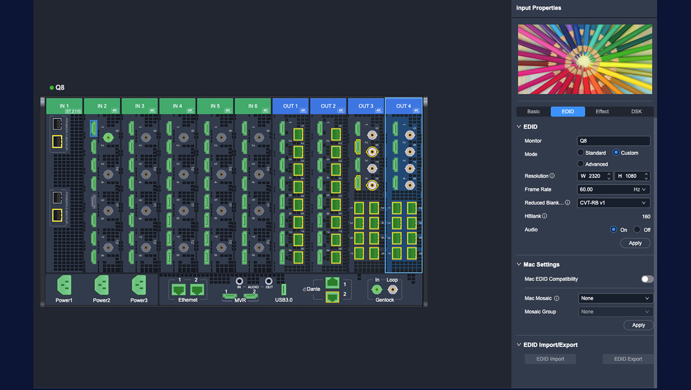
4. EDID Features in the PixelFlow Software
4.1 Input and Output EDID Configuration
The ability to customize EDID is one of the major advantages of the PIXELHUE product family. Input:
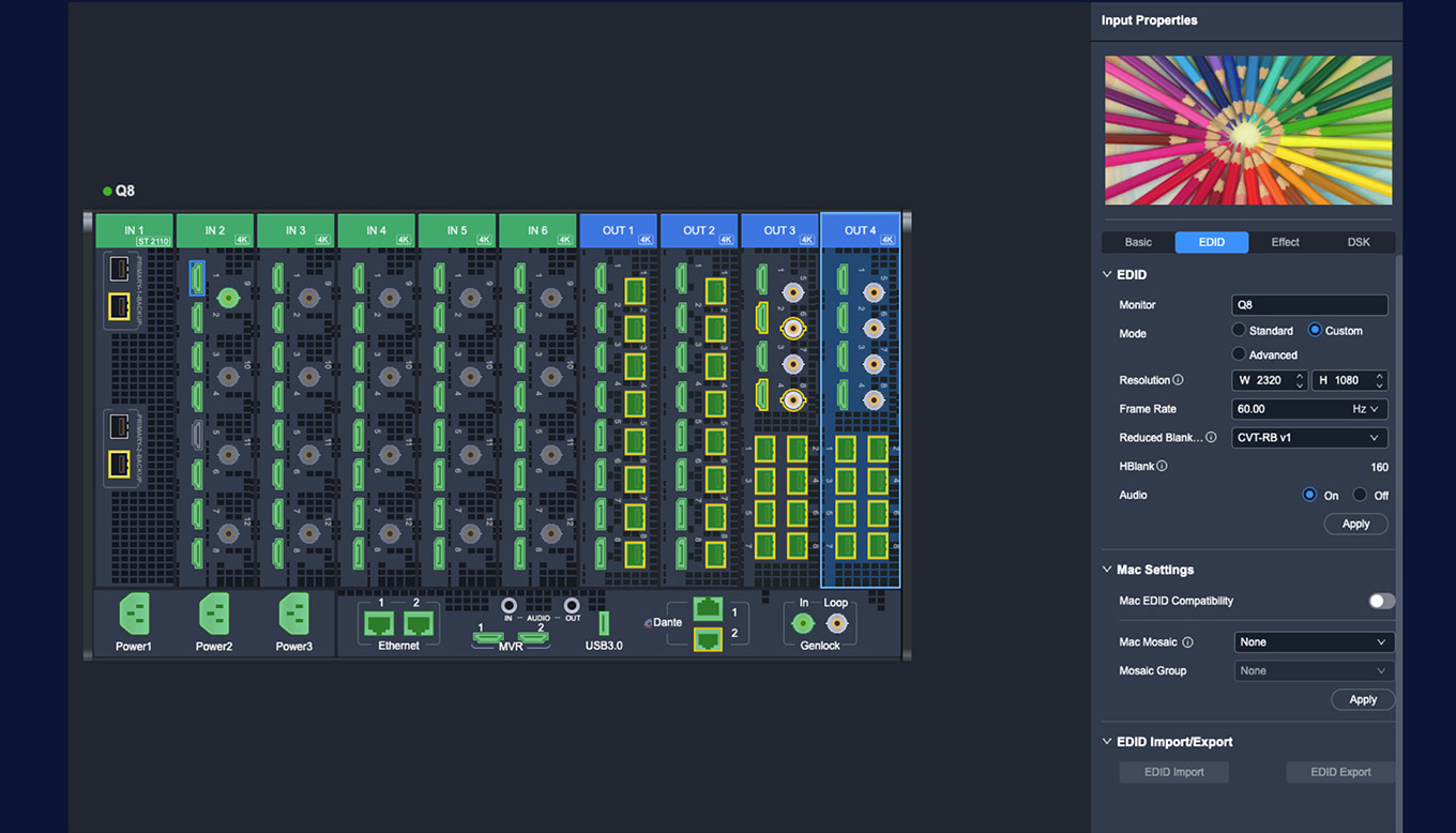
Clicking on any individual input port allows you to adjust its EDID parameters.
Starting from version 1.8.0, PixelFlow supports three configuration modes for input EDID:
• Standard Mode:Provides quick selection of common resolutions and timing standards such as
DMT, CEA, CVT-RB V1, and SMPTE.
• Custom Mode:Allows manual entry of resolution parameters and selection of different Reduced Blanking formats.
• Supports defining extreme custom dimensions up to 8192 × 600 or 800 × 7680.
• Advanced Mode
Intended for configuring non-standard timings and scenarios requiring precise bandwidth control.
• Users can edit each parameter individually, including:H Total / H Active / H Front Porch / H Sync / H Polarity
• V Total / V Active / V Front Porch / V Sync / V Polarity
• Frame Rate
These settings can be used in conjunction with the timing parameter tables for accurate configuration.
PixelFlow also supports EDID export and import, enabling flexible reuse and management of EDID profiles.
Output:
The EDID configuration options for output ports are the same as those for input ports, offering Standard, Custom, and Advanced modes. One important note:
If an output port is already being used as part of a video canvas, modifying its EDID from the DEVICE interface requires removing the canvas first.
Alternatively, EDID can be configured directly from the Screen interface without removing the layout.
Note: (Starting from version 1.8.0, PIXELHUE switchers that support audio provide independent audio-
enable switches for both input and output. However, in Custom Mode, if Hblank < 110, audio cannot be
enabled due to bandwidth and timing constraints.)
enable switches for both input and output. However, in Custom Mode, if Hblank < 110, audio cannot be
enabled due to bandwidth and timing constraints.)
4.2 Mac EDID Compatibility & Mosaic Output

Because macOS imposes much stricter requirements on EDID-including color characteristics, timing accuracy, and multi-display consistency-it is also far more prone to compatibility issues compared with typical devices.
To address this, starting from version 1.5.0, we introduced Mac EDID Compatibility Mode, ensuring stable display output, correct formatting, and consistent splicing on Mac devices.
During real-world playback scenarios, it is common for users to require a Mac to output two synchronized video signals that together form a larger canvas.
Beginning from version V1.7.1, PixelFlow introduced an important update specifically for this workflow.
For two identical interface types connected from the same Mac, users can independently assign them as “Left” and “Right.”
Once applied, macOS will automatically output two synchronized, left-right spliced signals.When using this feature, the following conditions must be satisfied: