Video Processor Delay
1. Preface
Video processing equipments on the market today, such as multimedia servers, broadcasting director stations, video switchers, and LEDsending cards, often introduce processing delays. The causes, testing methods, and measures of video processing delays are the focus of
customer attention.
2. Image Refresh Principle
To understand image delay, one needs to know the principle of image refresh. Image refresh involves many parameters: VTotal representsthe total number of rows scanned for a frame of image, HTotal represents the total number of columns scanned for a row of image,
VActive represents the number of valid display rows for a frame of image, and HActive represents the number of valid display columns for
a row of image. Taking the 1080P@60fps VESA timing standard as an example, Vtotal is 1125, HTotal is 2200, VActive is 1080, and
HActive is 1920. As shown in the Figure 2-1
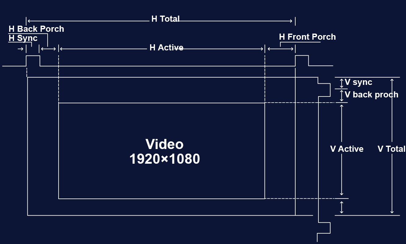
Figure 2-1 Video display timing introduction
All video display interfaces, such as HDMI and DP, transmit pixel data based on units of time. Taking 1080P@60fps as an example, the
refresh rules and timing for a frame, a line, and a pixel are shown in the Figure 2-2.
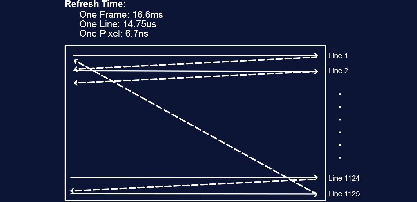
Figure 2-2 Video transmission and refresh mechanism
3. The Reason for Delay
In video processing equipment, the processing delay comes from "resolution change", including input source deinterlacing, image scaling,interface rotation, and input and output timing synchronization. However, in the processing system, there is no single functional module
that manifests the synchronization of input and output timing, and its delay effect caused by windowing will be combined.
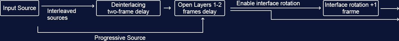
Figure 3 -1 PIXELHUE Q8 latency overview
3.1 Introduction to image scaling
Video switchers typically have a 1-2 frame delay. That is because their internal layer supports scaling, disrupting the timing relationship
between the input source and the output video.
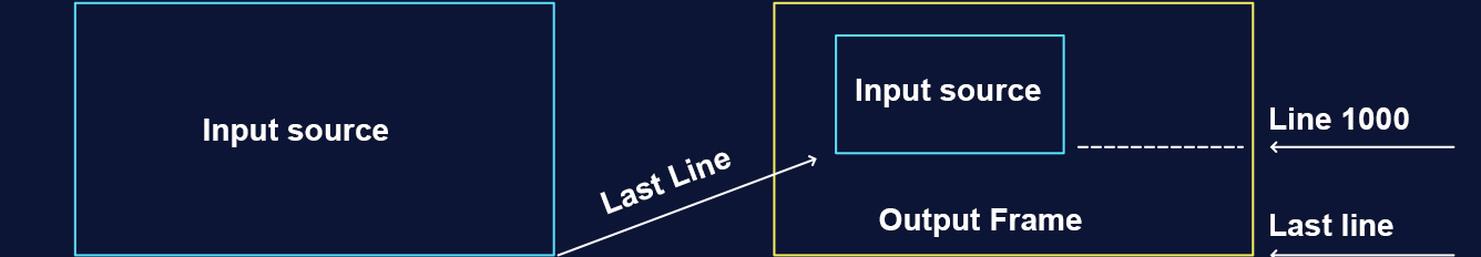
Figure 3-2 Input source windowing on the output canvas
3.2 Introduction to input source deinterlacing
In the early days of television, interlacing technology was used to reduce the amount of data that needed to be sent for each image.
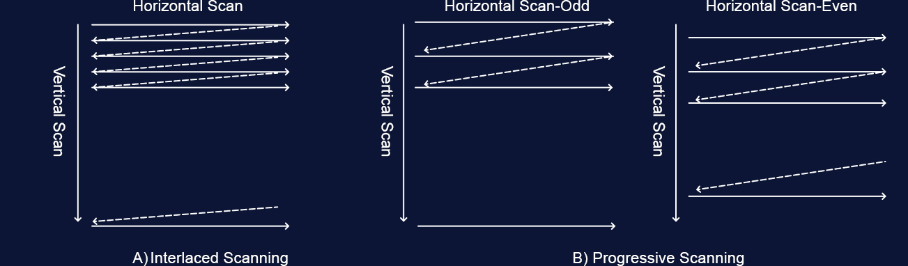
Figure 3-3 Progressive and interlaced image scanning methods
Interlaced scanning alternately scans odd and even lines in each frame, and the human eye perceives a complete image instead of two
half images.
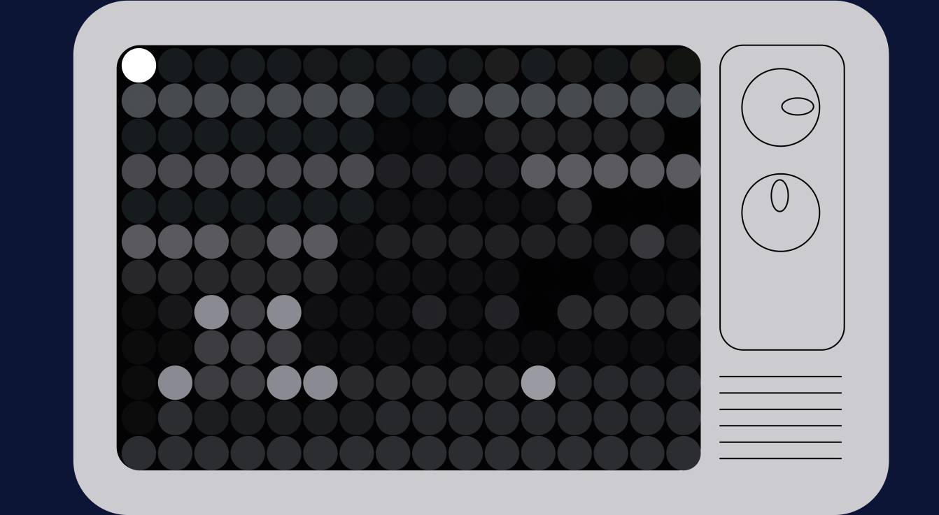
Figure 3-4 Animatio of interlaced image scanning
Since the odd field and the even field are extracted separately from two continuously acquired frames, if an odd field and an even field
image are simply spliced together, the horizontal movement will cause the two fields to not perfectly overlap.
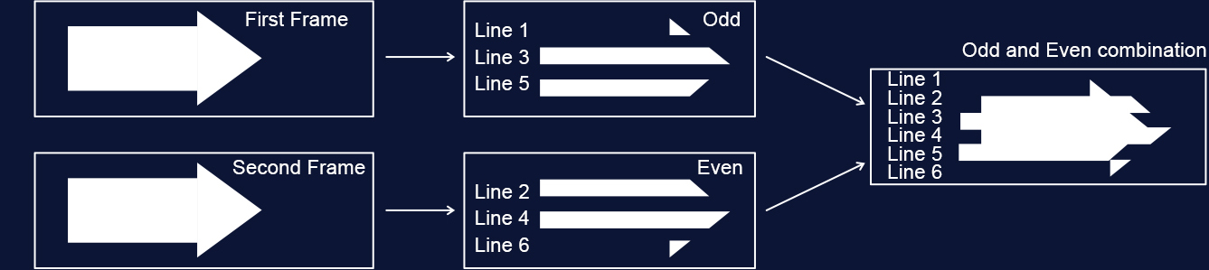
Figure 3-5 Demonstration of the effect of overlapping odd and even fields of interlaced images
In order to achieve a similar effect to progressive images and no jagged edges, all PIXELHUE products use a high-performance
deinterlacing algorithm based on motion adaptation. This algorithm needs to interpolate the missing images in each field based on the
motion information difference of the image content of the odd and even fields. This algorithm generates an updated progressive image
after capturing two frames, resulting in a two-frame delay. However, the processing quality is superior compared to a basic real-time
algorithm.
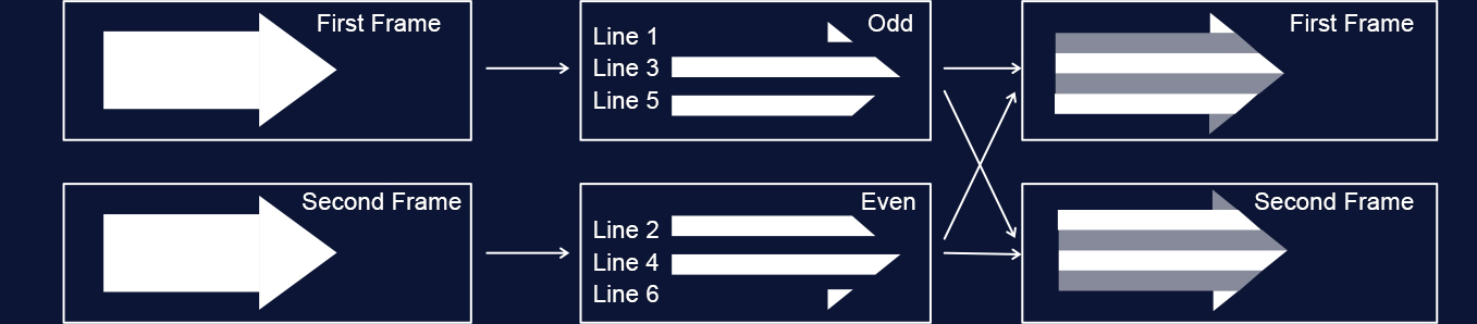
Figure 3-6 Motion adaptive deinterlacing effect
3.3 Output interface rotation
Image rotation is widely used in flight information broadcast, advertising screens and other application scenarios. Since the image
scanning mechanism of the display cannot be changed, when the display needs to be placed vertically, the material production is
produced according to the normal viewing angle, and the processor needs to rotate the image content in the opposite direction according
to the rotation angle of the display, and then refresh the image.
Since the timing of internal image content production and the timing of actual interface output are reversed, it is necessary to store the
produced video content in the memory and re-read it for display according to the interface refresh timing. Therefore, the interface rotation
will introduce a fixed one-frame delay.

Figure 3-7 Rotation Processing Diagram
4. Extended generation instructions
4.1 When input and output frame rates are consistent
When the input and output frame rates are similar or synchronized, windowing the output canvas will cause a 1-2 frame delay. Maintaining
strict synchronization can achieve a fixed 1 frame delay.
4.1.1 When approaching
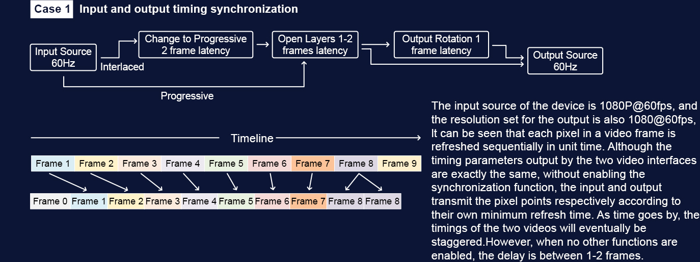
Figure 4-1
4.1.2 When synchronization is enabled
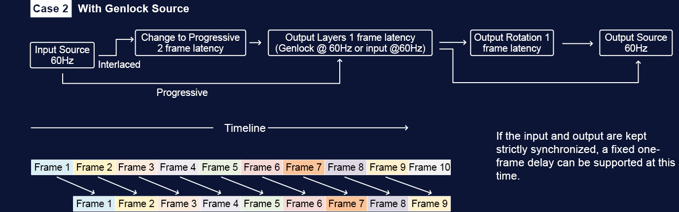
Figure 4-2
4.1.3 When the input frame rate is faster than the output frame rate
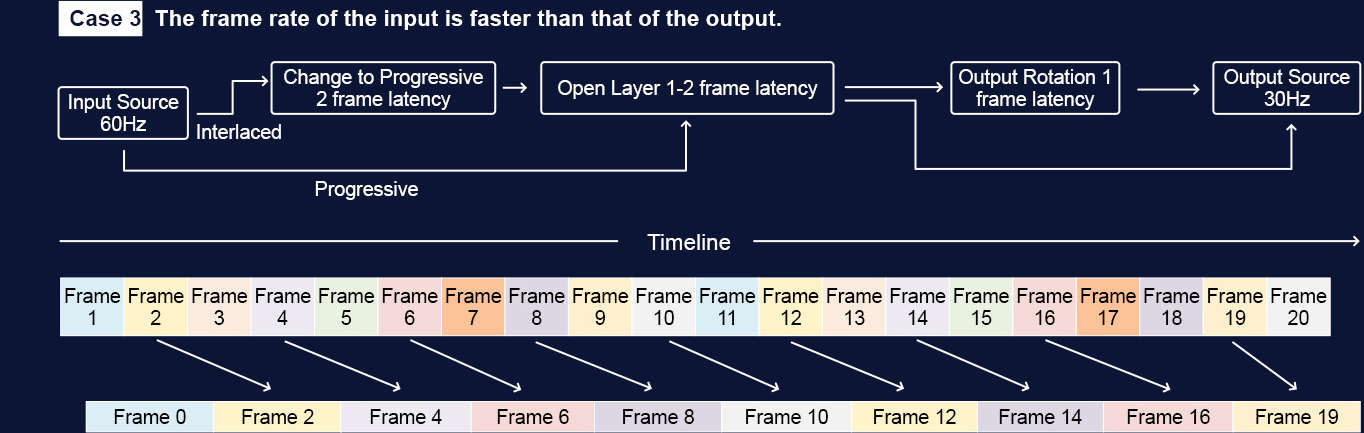
Figure 4-3
It shows that the input source frame rate is 2.X times that of the output frame rate, greater than twice but less than three times. lt can be
seen from the figure that as time accumulates, the delay from the input to the output will gradually increase and eventually jump back to a
one-frame delay, but the maximum is no more than a two-frame delay. At this time, one frame is based on the input source frame rate, In
the figure, there is a nearly two-frame delay when refreshing Frame 16, and a nearly one-frame delay when refreshing Frame 19, From
Frame 2 to Frame 16. the delay is gradually increasing, If the input source frame rate is 1.X times that of the output frame rate, less than
twice and greater than once, then the delay will gradually decrease from 2 frames to 1 frame and eventually become 2 frames again.
4.1.4 When the input frame rate is slower than the output frame rate
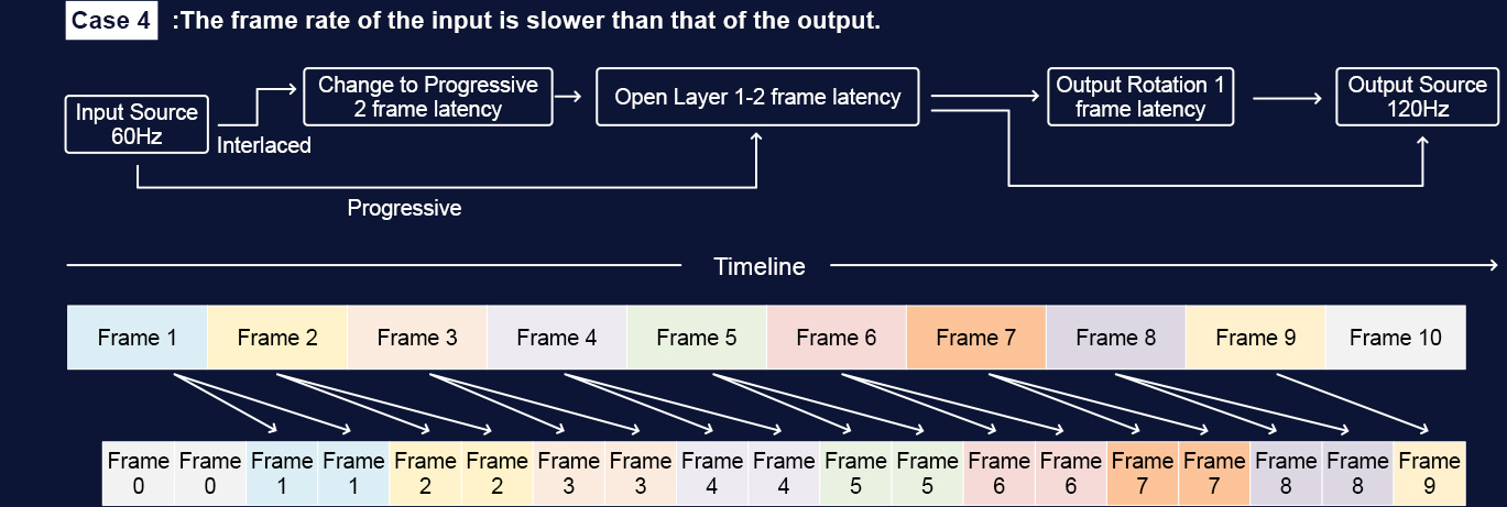
Figure 4-4
It can be seen here:
1. In most cases, the input source will be displayed twice repeatedly, but there will be a situation where one frame is displayed three times
at intervals. lf the output is close to twice the input frame rate but slightly less than twice, there will be a situation where one frame is
displayed once at intervals. The more absolutely accurate the relationship between the input and output frame rates,. the longer the
interval of such a situation. lf the output and input frame rate ratio is an absolute two times relationship, then each frame will be displayed
twice repeatedly and the delay time is fixed.
2. lt can be seen in the figure that the delay of the input source picture varies from large to small, The minimum delay occurs when
refreshing Frame 7. which is only one frame, but the delay of the next frame Frame 8 immediately becomes larger. approaching 1.5
frames
In short, regardless of the relationship between input and output frame rate, the display delay is between 1 and 2 frames relative to the
input source, and in the case of non-fixed magnification relationship, increasing the input or output refresh rate may not have an obvious
effect. To achieve optimal display performance, it is important to first ensure input and output synchronization, and then consider the
relationship between output bandwidth and input bandwidth, as well as the frame rate settings.
5. Latency Test
Generally, video processor manufacturers want to reduce processing latency because it not only meets customer needs but also reduces
memory consumption.
Software timer is a common test method, often used for comparison test of processing performance between devices, but the delay of a
single device is only for reference and cannot represent the absolute delay, as it cannot be completely synchronized with the video
interface. During the test, it is necessary to ensure that the timing from the input source to the display device and the processing device is
consistent, and the output timing of the processing device is synchronized.
When using professional hardware testing equipment such as LEO BODNAR’s 4K Lag Tester and Input Lag Tester, one needs to pay
attention to output synchronization and environmental settings to ensure the accuracy of the test results.
5.1 Latency Test
First of all, it is important to note that video processor manufacturers generally strive to minimize processing delay more than anyone else.
Besides meeting customer demands for low latency, another key reason is that the greater the video delay, the higher the memory
consumption. When complex video processing is not required, there is no need to use memory to store video images. After all, a 4K image
consumes about 265Mb of memory space, not to mention that the number of layers inside the video processor is quite rich.
Currently, there are two main ways to test system delay: software timer and professional hardware testing equipment.
5.2 Software Timer Test
The most commonly used testing method is the software timer, which typically includes settings for both seconds and frame rate.
Figure 5-1 Software timer interface

The software timer method is generally used for comparing the processing performance between devices. This method is only used as a
reference for testing the delay of a single device and cannot represent the absolute delay of the device. The main reason is that even if
the frame counter is set to be consistent with the output frame rate, the software timer cannot increase frame by frame in sync with the
video interface, and there may be a jump every 2 frames.
The basic environment for testing product delay by using software counters is as follows:
Figure 5-2 Software timer test link diagram
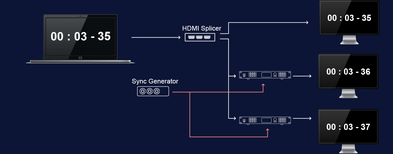
Use a distributor to send the same input source to the display and different processing devices, ensuring that the sources reaching the
display device and the processing device are time-coordinated.
The Genlock generator is given to all processing devices, and the synchronization function of the processing devices is turned on,
ensuring that the output timing of all processors is consistent. As can be seen from Figure 2-6, when the output timing of multiple
processing devices has no relationship with the input timing, the output delay fluctuates between 1-2 frames. At this time, there is a 1-
frame delay difference between the two processing devices, which cannot reflect the delay performance of the processor.
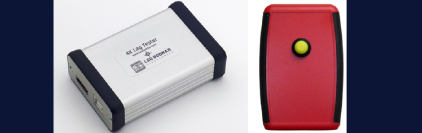
5.3 Professional hardware testing equipment
Currently, the devices on the market that can be used for video processing delay testing include LEO BODNAR’s 4K Lag Tester and Input
Lag Tester.
Figure 5-3 Dedicated delay tester
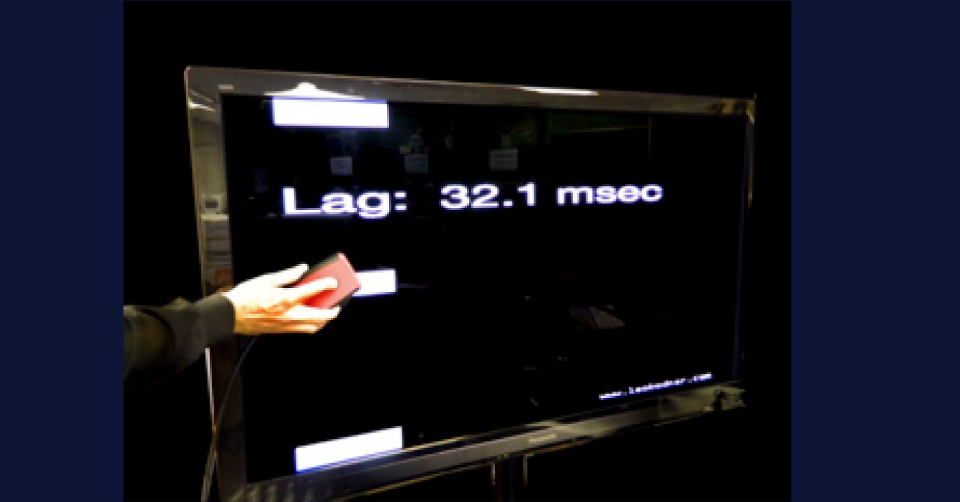
Here’s how to use them:
Plug the tester’s HDMI output into the TV and the device under test.
With the processor output connected to the display device, hold down the button and wait for the test screen to appear.
Position the device on the screen with the photosensor facing one of the three reference marks shown.
Read the measurement results from the screen.
Figure 5-4 Input Lag Tester test results
Test Notes:
When using this tester, it is best to synchronize the output to the input to be tested to eliminate test result deviation caused by different
input and output timings.
To ensure accurate results, it is recommended to set the screen to maximum brightness and reduce ambient lighting as much as possible.
6. Summarize
PIXELHUE’s video processor has achieved industry-leading latency while ensuring optimal display effects, and will continue to explore
ways to reduce latency.